- 您现在的位置:买卖IC网 > Sheet目录1194 > ADT7468ZEVB (ON Semiconductor)BOARD EVAL FOR ADT7468
�� �
�
�ADT7468�
�For� applications� where� the� monitoring� cycle� time� is� important,�
�it� can� be� calculated� easily.�
�The� measured� channels� are�
�Bit� 6� (R2T)� =� 1,� Remote� 2� temperature� high� or� low� limit� has�
�been� exceeded.�
�Bit� 5� (LT)� =� 1,� local� temperature� high� or� low� limit� has� been�
�?�
�?�
�?�
�?�
�Four� dedicated� supply� voltage� inputs�
�Supply� voltage� (V� CC� pin)�
�Local� temperature�
�Two� remote� temperatures�
�exceeded.�
�Bit� 4� (R1T)� =� 1,� Remote� 1� temperature� high� or� low� limit� has�
�been� exceeded.�
�Bit� 3� (5� V)� =� 1,� 5� V� high� or� low� limit� has� been� exceeded.�
�Bit� 2� (V� CC� )� =� 1,� V� CC� high� or� low� limit� has� been� exceeded.�
�As� mentioned� previously,� the� ADC� performs� round-robin�
�conversions� and� takes� 11� ms� for� each� voltage� measurement,�
�12� ms� for� a� local� temperature� reading,� and� 39� ms� for� each�
�remote� temperature� reading.� The� total� monitoring� cycle� time�
�for� averaged� voltage� and� temperature� monitoring� is,� therefore,�
�nominally�
�(5� � 11)� +� 12� +� (2� � 39)� =� 145� ms�
�Fan� TACH� measurements� are� made� in� parallel� and� are� not�
�synchronized� with� the� analog� measurements� in� any� way.�
�STATUS� REGISTERS�
�The� results� of� limit� comparisons� are� stored� in� Status� Registers� 1�
�and� 2.� The� status� register� bit� for� each� channel� reflects� the� status�
�of� the� last� measurement� and� limit� comparison� on� that� channel.�
�If� a� measurement� is� within� limits,� the� corresponding� status�
�register� bit� is� cleared� to� 0.� If� the� measurement� is� out-of-limit,�
�the� corresponding� status� register� bit� is� set� to� 1.�
�The� state� of� the� various� measurement� channels� can� be� polled� by�
�reading� the� status� registers� over� the� serial� bus.� In� Bit� 7� (OOL)� of�
�Status� Register� 1� (Reg.� 0x41),� 1� means� that� an� out-of-limit� event�
�has� been� flagged� in� Status� Register� 2.� This� means� that� the� user�
�also� needs� to� read� Status� Register� 2.� Alternatively,� Pin� 10� or�
�Pin� 14� can� be� configured� as� an� SMBALERT� output.� This� hard�
�interrupt� automatically� notifies� the� system� supervisor� of� an� out-�
�of-limit� condition.� Reading� the� status� registers� clears� the� appro-�
�priate� status� bit� as� long� as� the� error� condition� that� caused� the�
�interrupt� has� cleared.� Status� register� bits� are� sticky.� The� status�
�bits� are� referred� to� as� sticky,� because� they� remain� set� until� read�
�by� software.� Whenever� a� status� bit� is� set,� indicating� an� out-of-�
�limit� condition,� it� remains� set� even� if� the� event� that� caused� it�
�has� ceased� (until� read).� The� only� way� to� clear� the� status� bit� is� to�
�read� the� status� register� after� the� event� has� ceased.� Interrupt�
�status� mask� registers� (0x74,� and� 0x75)� allow� individual� inter-�
�Bit� 1� (V� CCP� )� =� 1,� V� CCP� high� or� low� limit� has� been� exceeded.�
�Bit� 0� (2.5� V)� =� 1,� 2.5� V� high� or� low� limit� has� been� exceeded.�
�Status� Register� 2� (Reg.� 0x42)�
�Bit� 7� (D2)� =� 1,� indicates� an� open� or� short� on� D2+/D2–� inputs.�
�Bit� 6� (D1)� =� 1,� indicates� an� open� or� short� on� D1+/D1–� inputs.�
�Bit� 5� (F4P)� =� 1,� indicates� Fan� 4� has� dropped� below� minimum�
�speed.� Alternatively,� indicates� that� the� THERM� limit� has� been�
�exceeded,� if� the� THERM� function� is� used.�
�Bit� 4� (FAN3)� =� 1,� indicates� Fan� 3� has� dropped� below� minimum�
�speed.�
�Bit� 3� (FAN2)� =� 1,� indicates� Fan� 2� has� dropped� below� minimum�
�speed.�
�Bit� 2� (FAN1)� =� 1,� indicates� Fan� 1� has� dropped� below� minimum�
�speed.�
�Bit� 1� (OVT)� =� 1,� indicates� a� THERM� overtemperature� limit� has�
�been� exceeded.�
�Bit� 0� (12V/VC)� =� 1,� indicates� a� 12� V� high� or� low� limit� has� been�
�exceeded.� If� the� VID� code� change� function� is� used,� this� bit�
�indicates� a� change� in� VID� code� on� the� VID0� to� VID5� inputs.�
�INTERRUPTS�
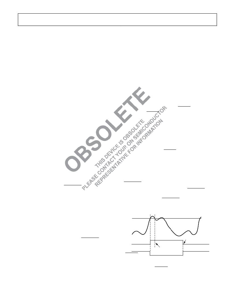
�SMBALERT� Interrupt� Behavior�
�The� ADT7468� can� be� polled� for� status,� or� an� SMBALERT�
�interrupt� can� be� generated� for� out-of-limit� conditions.� It� is�
�important� to� note� how� the� SMBALERT� output� and� status� bits�
�behave� when� writing� interrupt� handler� software.�
�HIGH� LIMIT�
�TEMPERATURE�
�CLEARED� ON� READ�
�rupt� sources� to� be� masked� from� causing� an� SMBALERT.� How-�
�ever,� if� one� of� these� masked� interrupt� sources� goes� out-of-limit,�
�its� associated� status� bit� is� set� in� the� interrupt� status� registers.�
�Status� Register� 1� (Reg.� 0x41)�
�Bit� 7� (OOL)� =� 1,� denotes� a� bit� in� Status� Register� 2� is� set� and�
�“STICKY”�
�STATUS� BIT�
�SMBALERT�
�TEMP� BACK� IN� LIMIT�
�(STATUS� BIT� STAYS� SET)�
�(TEMP� BELOW� LIMIT)�
�Status� Register� 2� should� be� read.�
�Rev.� 3� |� Page� 23� of� 81� |� www.onsemi.com�
�Figure� 28.� SMBALERT� and� Status� Bit� Behavior�
�发布紧急采购,3分钟左右您将得到回复。
相关PDF资料
ADT7473ZEVB
BOARD EVALUATION FOR ADT7473
ADT7475EBZEVB
BOARD EVALUATION FOR ADT7475
ADT7476EBZEVB
BOARD EVALUATION FOR ADT7476
ADT7490ZEVB
BOARD EVALUATION FOR ADT7490
ADZS-21262-1-EZEXT
BOARD DAUGHTER FOR ADSP-21262
ADZS-BF-EZEXT-1
BOARD DAUGHTER ADSP-BF533/561KIT
ADZS-BFAV-EZEXT
BOARD DAUGHT ADSP-BF533,37,61KIT
ADZS-BFSHUSB-EZEXT
BOARD DAUGHTER EZ EXTENDER
相关代理商/技术参数
ADT7470
制造商:AD 制造商全称:Analog Devices 功能描述:Temperature Sensor Hub and Fan Controller
ADT7470_13
制造商:AD 制造商全称:Analog Devices 功能描述:Temperature Sensor Hub and Fan Controller
ADT7470ARQ
制造商:Analog Devices 功能描述:Temp Sensor Digital Serial (I2C) 16-Pin QSOP
ADT7470ARQ-REEL
制造商:Rochester Electronics LLC 功能描述: 制造商:Analog Devices 功能描述:
ADT7470ARQ-REEL7
制造商:Analog Devices 功能描述:Temp Sensor Digital Serial (I2C) 16-Pin QSOP T/R
ADT7470ARQZ
功能描述:IC SENSOR TEMP FAN CTRLR 16QSOP RoHS:是 类别:集成电路 (IC) >> PMIC - 热管理 系列:- 标准包装:3,000 系列:- 功能:温度开关 传感器类型:内部 感应温度:85°C 分界点 精确度:±6°C(最小值) 拓扑:ADC(三角积分型),比较器,寄存器库 输出类型:开路漏极 输出警报:是 输出风扇:是 电源电压:2.7 V ~ 5.5 V 工作温度:-55°C ~ 125°C 安装类型:表面贴装 封装/外壳:SC-74A,SOT-753 供应商设备封装:SOT-23-5 包装:带卷 (TR) 其它名称:ADT6501SRJZP085RL7-ND
ADT7470ARQZ-REEL
功能描述:IC SENSOR TEMP FAN CTRLR 16QSOP RoHS:是 类别:集成电路 (IC) >> PMIC - 热管理 系列:- 标准包装:2,500 系列:SilentSense™ 功能:温度监控系统(传感器) 传感器类型:内部和外部 感应温度:-55°C ~ 125°C,外部传感器 精确度:±2°C 本地(最大),±3°C 远程(最大) 拓扑:ADC(三角积分型),比较器,寄存器库 输出类型:I²C?/SMBus? 输出警报:是 输出风扇:是 电源电压:2.7 V ~ 5.5 V 工作温度:-55°C ~ 125°C 安装类型:表面贴装 封装/外壳:8-TSSOP,8-MSOP(0.118",3.00mm 宽) 供应商设备封装:8-MSOP 包装:带卷 (TR) 其它名称:MIC284-2BMMTRMIC284-2BMMTR-ND
ADT7470ARQZ-REEL7
功能描述:IC SENSOR TEMP FAN CTRLR 16QSOP RoHS:是 类别:集成电路 (IC) >> PMIC - 热管理 系列:- 标准包装:2,500 系列:SilentSense™ 功能:温度监控系统(传感器) 传感器类型:内部和外部 感应温度:-55°C ~ 125°C,外部传感器 精确度:±2°C 本地(最大),±3°C 远程(最大) 拓扑:ADC(三角积分型),比较器,寄存器库 输出类型:I²C?/SMBus? 输出警报:是 输出风扇:是 电源电压:2.7 V ~ 5.5 V 工作温度:-55°C ~ 125°C 安装类型:表面贴装 封装/外壳:8-TSSOP,8-MSOP(0.118",3.00mm 宽) 供应商设备封装:8-MSOP 包装:带卷 (TR) 其它名称:MIC284-2BMMTRMIC284-2BMMTR-ND